|
Construction
of an Evaporator for Syrup Production
This page is divided into two
parts. In the first part, the basic outline for
construction of an evaporator is laid out. In the second
part, photographs of a skimming trough that may be built
onto the sides of the evaporator are shown.
Part I. Basic Outline
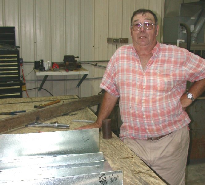
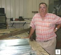 I wish to gratefully acknowledge
Mr. Billy Poitevint (Pelham, Georgia; Slide
1), who built
many of the evaporators in use in the Southeast, including
the ones in use at Mule Day and by
Felix Horne, a
commercial syrup maker and about which more in Part II. As
far as I am aware, Mr. Poitevint is the last commercial
artisan in the North Florida/South Georgia region to have
made evaporators. Mr. Poitevint generously gave I wish to gratefully acknowledge
Mr. Billy Poitevint (Pelham, Georgia; Slide
1), who built
many of the evaporators in use in the Southeast, including
the ones in use at Mule Day and by
Felix Horne, a
commercial syrup maker and about which more in Part II. As
far as I am aware, Mr. Poitevint is the last commercial
artisan in the North Florida/South Georgia region to have
made evaporators. Mr. Poitevint generously gave  his time
to me one afternoon and made a mock-up evaporator (Slide
1), from which the drawings were made by Ken Womble (Slide
2) to whom I am also in debt. As usual, I wish to thank
Ken Christison for encouragement. (Mr. Poitevint used
galvanized metal for the purpose of demonstration, but
currently commercial evaporators are made from food-grade
stainless steel (20-24 gauge according to Morris Bitzer;
18 gauge for batch pans)). his time
to me one afternoon and made a mock-up evaporator (Slide
1), from which the drawings were made by Ken Womble (Slide
2) to whom I am also in debt. As usual, I wish to thank
Ken Christison for encouragement. (Mr. Poitevint used
galvanized metal for the purpose of demonstration, but
currently commercial evaporators are made from food-grade
stainless steel (20-24 gauge according to Morris Bitzer;
18 gauge for batch pans)).
Although Slides 3-5 represent a
sequence in the construction of an evaporator, the slides
are designed to be viewed together with a minimum
narrative.
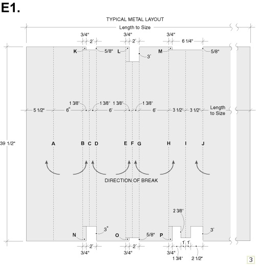
Labels A-J in the initial metal
layout (Slide
3) indicates the breaks (dotted lines) in
the metal sheet. This layout shows one end (formed by a
90° break at Label A), and the repeating baffle patterns
(two low baffles, peaks at Label C and Label F; and one
high baffle, peak at Label I). This three-baffle pattern
is repeated for the length of the evaporator, generally 12-18 feet. All dimensions are nominal, typical and are an
illustration of a "to fit" fabrication; for
example, the low baffles are sized for the illustration at
1 3/8 inches high, but other designs called for them to be
higher or lower, and here, no allowance was been made for
the metal taken up by the bends.
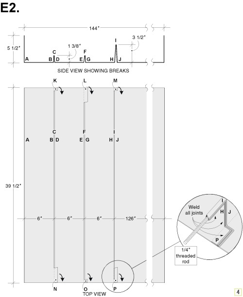
Slide 4 shows the metal sheet
after the breaks are made. In the side view (at top), the
baffles are spread out for illustration. In an actual
fabrication, the center bend (e.g., Label C) is 180° and
the other bends are 90°. Once the bends in the baffles
are made, a ¼-inch threaded rod is run through the top of
the high baffle (Label I, detail at bottom right). Then,
all tabs (e.g., Label K and Label N) are pressed flat and
welded, as are the ends of all baffles.
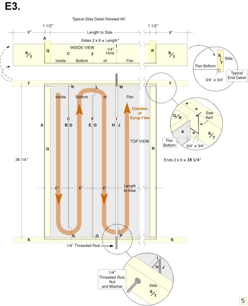
The evaporator has four wooden
sides (Slide 5); poplar was preferred by Mr. Poitevint,
but cypress was also used. Near each end of the side rails
(see Label T, detail at right), an inside vertical kerf is
made into which the vertical metal end (Label A) is
inserted. Then, the wooden evaporator end (2 x 6",
Label Q) is placed parallel and inside the metal end
(Label A). The side rail (Label S) is a 2 x 6 (inch), cut
to length. A ¾ x ¾ inch cut-out of the inside bottom of
the rail (top detail, Slide
5) is removed. The edge of the
pan is fit into the cut-out so that the baffles are flush
with the side rails. Then, the cut-out is replaced, using
nails or other fasteners, and the threaded rods are bolted
in place (lower detail, Slide
5). Historically, cotton
fiber was stuffed into the metal to wood interfaces, but
Mr. Poitevint used Lexel caulk in the last evaporators he
made. For a few days before use, evaporator were filled
with water to swell the wood, decreasing the likelihood of
leaks.
Part II. Photographs of a
Skimming Trough
The purpose of this part is to
illustrate how the basic evaporator design shown above was
modified to include skimming troughs. I wish to gratefully
acknowledge Mr. Felix Horne (Metcalfe, Georgia), who
allowed me to make photographs of his evaporator and
include them here.
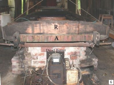
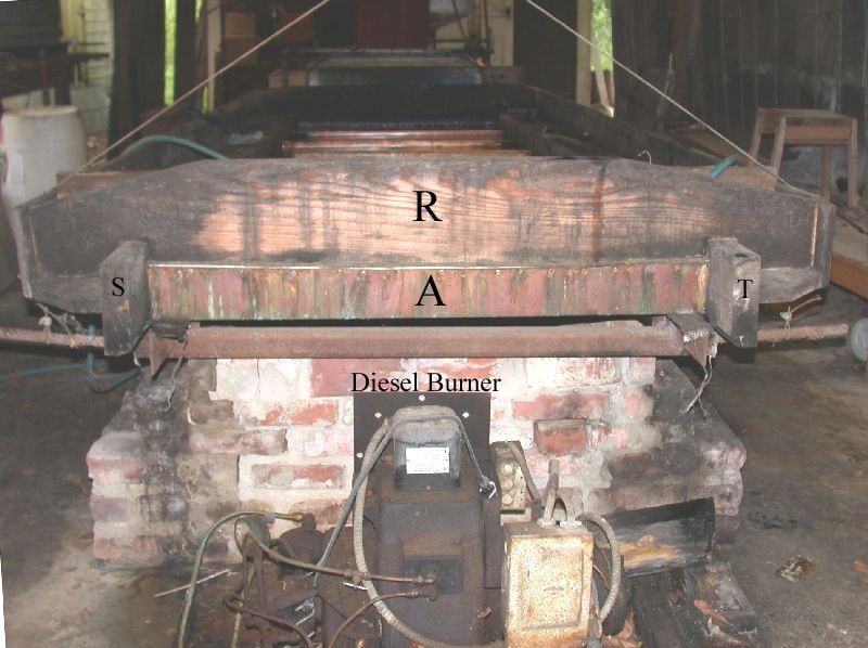
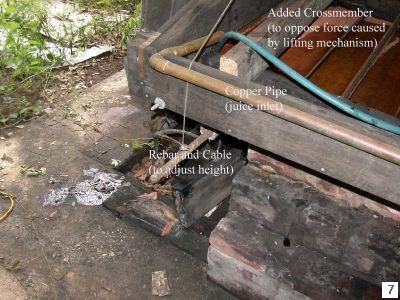
An overview of the evaporator
(Slide
6) is taken from the juice end. The labels in this
slide correspond to those used above, but note that the
designs of the wooden components are not identical, as
expected. The end of the evaporator metal (Label A) is
outside the wooden evaporator end (Label R). The skimming
troughs are built onto the evaporator, outside the
modified (inner) side rails (Label S and Label T). Another
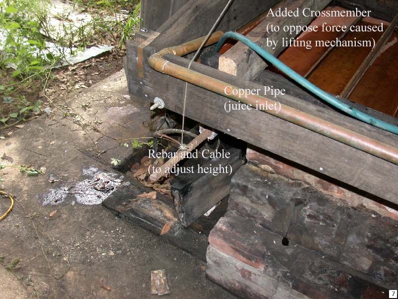
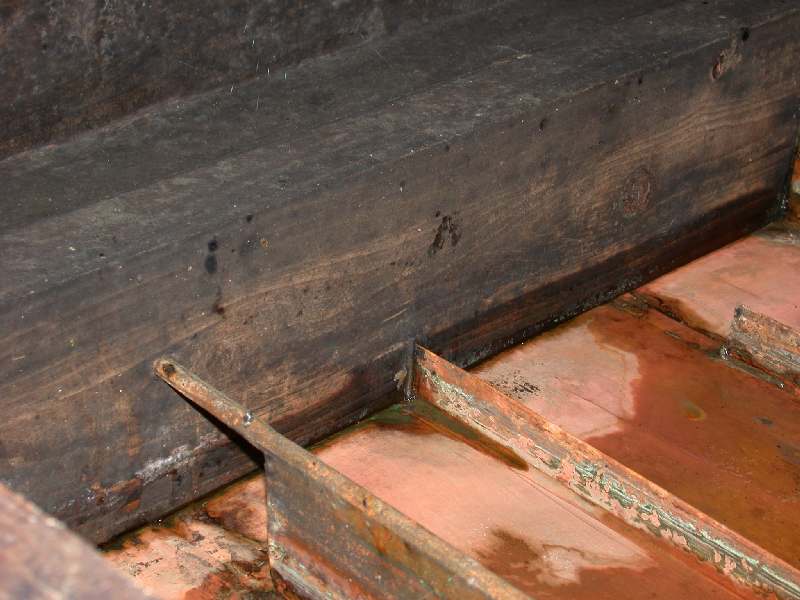
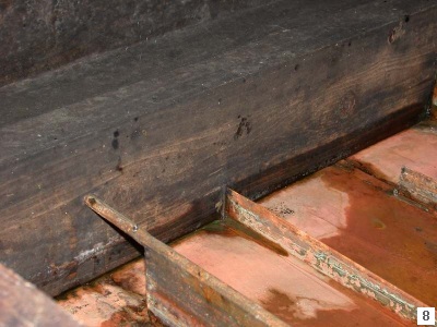
view of the juice end (Slide
7) shows how the height is
adjusted whereas Slide 8 show details of the baffles and
inner side rail.
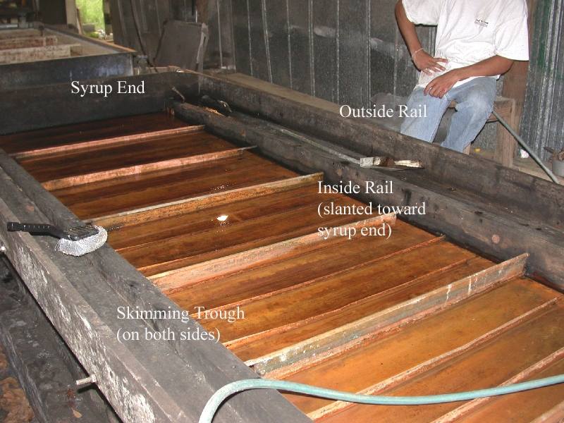
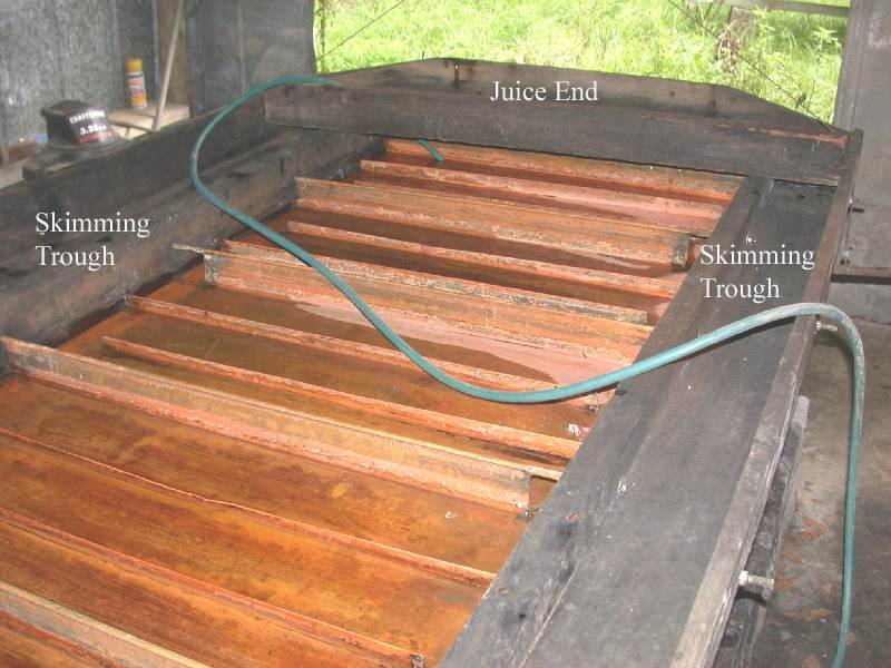
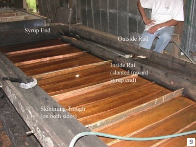
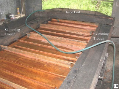
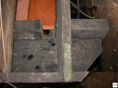
Two views of the skimming troughs
are shown in Slide 9 (taken toward the syrup end) and
Slide 10 (taken toward the juice end). The inside rails
are slanted downward toward the syrup end. Skimmings that
boil over into the trough are removed by a typical
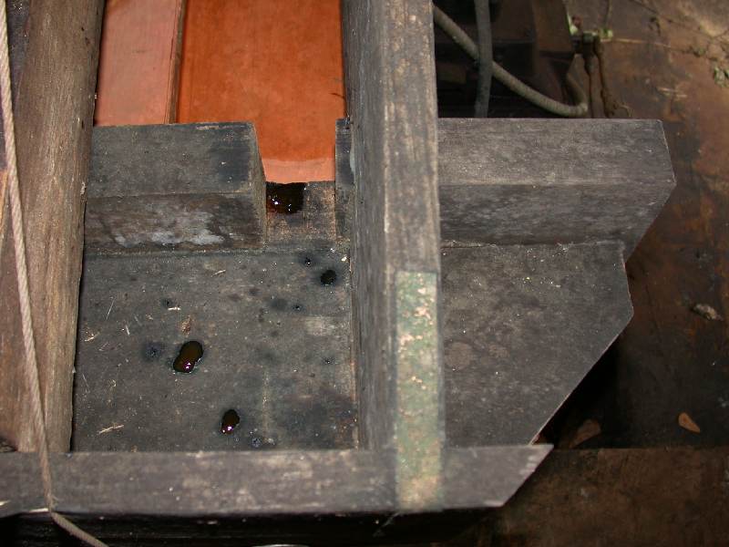
skimmer. The liquid in the skimming trough returns to the
juice ends via slots in the inner side rail (Slide
11).
In closing, I must make the usual
legal disclaimer. This page, a description of the
historical means of evaporator construction, is provided
for entertainment and education only; it is not a guide.
Construction and use of an evaporator should be done only
by qualified persons and may involve sharp, rapidly
moving, hot, and explosive materials. No liability is
assumed.
|